

Precautions for Use:
In addition to selecting the appropriate safety barrier for the intrinsically safe system, attention should be paid to the following aspects during use:
Firstly, pay attention to the capacitive and inductive reactance of cables and field devices. Intrinsic safety is a system-wide concept. Apart from the safety barrier needing to meet the required explosion-proof rating, the energy storage capacity of cables and field devices is also a critical issue. Engineers should pay particular attention to this issue, especially after parameter certification replaces system certification.
Secondly, ensure proper intrinsically safe grounding for the zener safety barrier, with a grounding resistance of less than 1 ohm.
Thirdly, intrinsically safe cables and non-intrinsically safe cables should be laid separately in different wire troughs and clearly labeled.
Fourthly, ensure power is turned off when making replacements.

Installation Guidelines:
The safety barrier should be installed in a safe area, and the environmental conditions should meet the "Operating Conditions" specified in the "Safety Barrier Selection Sample."
The connecting wires of the intrinsically safe (blue end) and non-intrinsically safe circuits of the isolated safety barrier should be laid separately in the wiring duct, each with its own independent protective sleeve. No other power lines, including those used by the intrinsically safe circuits, are allowed in the wiring ducts for the intrinsically safe side.
Wires leading to hazardous areas should be marked with blue and have a soft copper cross-sectional area of at least 0.5mm² and an insulation strength greater than 500V.
Before powering up and debugging the isolated safety barrier, ensure that its model, wiring method, and line polarity comply with the design and product requirements, as deviations may cause harm to personnel and equipment.
It is strictly prohibited to use a megger to test the insulation strength between terminals of the isolated safety barrier. To check the insulation strength of the system, first disconnect all the safety barrier wiring; otherwise, it may damage the internal circuitry of the safety barrier.
Before programming the safety barrier on-site, disconnect all wiring before connecting the programmer and then power it up for programming. Failure to do so may lead to adverse consequences.
Field instruments connected to the isolated safety barrier must have passed explosion-proof tests conducted by nationally recognized explosion-proof inspection departments and obtained explosion-proof certification.
When designing, installing, using, or maintaining isolated safety barriers, follow the instructions in this product manual as well as the relevant national standards such as "GB3836.15-2000 Electrical apparatus for explosive gas atmospheres - Part 15: Electrical installation in hazardous areas (other than mines)" and "GB50058-1992 Code for design of electric installations within explosion and fire hazard atmospheres."
A safety barrier, also known as a safety limiter, is an essential component in an intrinsically safe system.
Safety barriers are mainly divided into two categories: zener safety barriers and isolated safety barriers.
The core components of a zener safety barrier are zener diodes, current-limiting resistors, and fast-acting fuses.
An isolated safety barrier not only limits energy but also provides isolation. It comprises a circuit energy-limiting unit, a signal and power isolation unit, and a signal processing unit.
The primary function of a safety barrier is to limit current and voltage, ensuring that the energy available to field instruments remains within safe limits.
A safety barrier, also known as a safety retainer, serves as a safety interface in an intrinsically safe loop. It can bi-directionally transmit electrical signals between safe areas (non-intrinsically safe) and hazardous areas (intrinsically safe) while limiting the transfer of energy from the safe area to the hazardous area in case of a fault. Safety barriers generally come in two types: zener and isolated.
Intrinsically safe safety barriers are used in the design of intrinsically safe explosion-proof systems. They are installed in safe areas and contain both intrinsically safe and non-intrinsically safe circuits. By limiting the energy sent to the field intrinsically safe loop through current and voltage limiting circuits, they prevent hazardous energy from the non-intrinsically safe circuit from entering the intrinsically safe circuit. In an intrinsically safe explosion-proof system, they are known as associated apparatus and constitute an important part of the system.
Associated apparatus in an intrinsically safe explosion-proof system refers to electrical equipment installed in safe areas that connect intrinsically safe electrical equipment with non-intrinsically safe electrical equipment.
Since the safety barrier is designed as an energy-limiting interface between field devices and control room equipment, it ensures that the energy transmitted to field devices through it remains intrinsically safe, regardless of the normal or fault state of the control
相关文章
-
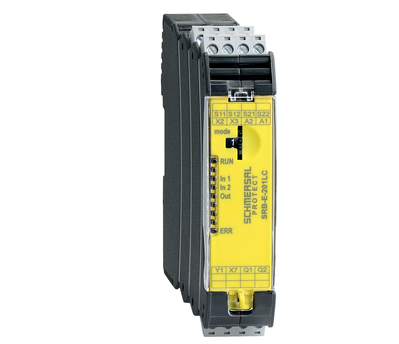
Schmersal Safety Relay Module SRB-E
Widely Applicable Safety Signal Processing The new generation of safety relay modules, the PROTECT SRB-E series, comes in 8 models, achieving safety ratings of Cat.4 / PLe (compliant with EN ISO 13849-1 standard) and SIL 3 (compliant...
-
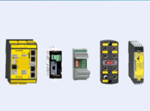
Schmersal Safety Installation System
Providing Optimal Solutions for Diverse Applications The new Schmersal safety installation system simplifies the rapid connection of safety switches to existing complex equipment systems, significantly reducing wiring errors and cost...
-
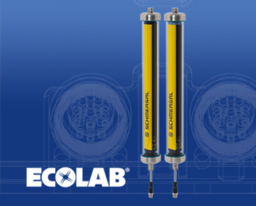
Schmersal SLC/SLG 440 IP69K Series Safety Light Curtains
Schmersal SLC/SLG 440 IP69K Series Safety Light Curtains, Ideal for the Food Industry The Schmersal SLC/SLG 440 IP69K Series: Hygienic and Durable Schmersal Group has developed a new series of safety light curtains and ba...
-

Schmersal Safety Light Curtain SLC44/COM BLE
Bluetooth Interface for Safety Light Curtains Schmersal Group has introduced the SLC440/COM, a pioneering safety light curtain equipped with a built-in Bluetooth Low Energy (BLE) interface. This photoelectric protective device (AOPD)...
-
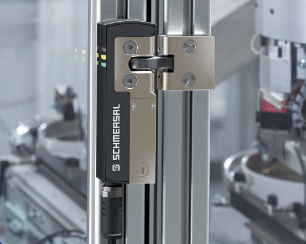
SCHMERSAL Introduces the World's Smallest Electromagnetic Safety Lock
The SCHMERSAL AZM40, measuring 119.5 x 40 x 20 mm, boasts the title of the world's smallest electromagnetic safety lock. This makes it especially suitable for small safety gates and flaps. Thanks to its 180° flexible actuator, the...
-
SCHMERSAL Modular Switch Platform HDS
SCHMERSAL Group has introduced a brand-new HDS series of switches tailored for the heavy industry. This modular product line, integrating multiple functions, finds extensive applications across various heavy industries. Based on a s...