

Xin Xiaochen has the advantage of supplying MTL4510 products at favorable prices. Welcome to send inquiries and purchase requests to our email 18070781367@163.com or add our WhatsApp +86 18278761660.
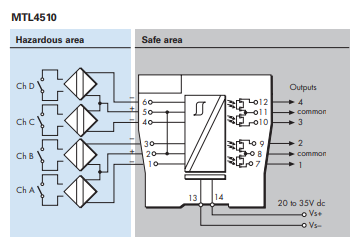
The MTL4510 enables four solid-state outputs in the safe area to be controlled by up to four switches or proximity detectors located in a hazardous area. Each pair of output transistors shares a common terminal and can switch +ve or –ve polarity signals. A range of module configurations is available (see Table 1) through the use of selector switches. When proximity detector modes are selected, LFD is enabled and the output switches to OFF if a line fault is detected.
SPECIFICATION
See also common specification
Number of channels
4, configured by switches
Location of switches
Zone 0, IIC, T6 hazardous area
Div 1, Group A hazardous location
Location of proximity detectors
Zone 0, IIC, T4-6 hazardous area if suitably certified
Div 1, Group A, hazardous location
Hazardous-area inputs Inputs
conforming to BS EN60947–5–6:2001 standards for proximity detectors (NAMUR)
Voltage applied to sensor
7 to 9V dc from 1kΩ ±10%
Input/output characteristics

Normal phase
Outputs closed if input > 2.1mA (< 2kΩ in input circuit)
Outputs open if input < 1.2mA (> 10kΩ in input circuit)
Hysteresis: 200µA (650Ω) nominal
Line fault detection (LFD) (when selected)
User-selectable via switches on the side of the unit.
Open-circuit alarm on if Iin < 50µA
Open-circuit alarm off if Iin > 250µA
Short-circuit alarm on if Rin < 100Ω
Short-circuit alarm off if Rin > 360Ω
Note: Resistors must be fitted when using the LFD facility with a contact input 500Ω to 1kΩ in series with switch 20kΩ to 25kΩ in parallel with switch
Safe-area outputs
Floating solid-state outputs compatible with logic circuits
Operating frequency: dc to 500Hz
Max. off-state voltage: ± 35V
Max. off-state leakage current: ± 50µA Max. on-state resistance: 25Ω
Max. on-state current: ± 50mA
LED indicators
Green: power indication
Yellow: four: on when output active
Red: LFD indication + faulty channel’s yellow LED flashes
Maximum current consumption 40mA at 24V (with all output channels energised)
Power dissipation within unit 0.96W at 24V, with 10mA loads
Safety description (each channel)
Uo=10.5V Io=14mA Po=37mW Um = 253V rms or dC
相关文章
-

MTL1141 isolator
MTL1144 voltage/current input isolator 1 channel for 1V/5V/10V and 20mA inputs The MTL1144 is a single channel signal converter which can accept 0-1V, 0-5V, 1-5V, 0-10V, 0-20mA and 4-20mA inputs and converts the signal to 4-20mA for...
-
MTL7798
MTL7798 Power feed and protection module The MTL7798 power feed module incorporates both voltage and current sense mechanisms to protect barrier circuits by activating a solid state trip mechanism when fault or overload conditions oc...
-
MTL7744
MTL7744 2 channel proximity sensor or switch inputs with solid state outputs A dual channel version of the MTL7742. This module provides two solid state interfaces for prox/switch inputs. Power is connected via the power bus. BASIC...
-
MTL7743
MTL7743 2 channel proximity sensor or switch input and relay outputs The MTL7743 is a dual channel switch/prox sensor input barrier with a relay interface. This module is ideal for applications where high channel packing densities ar...
-
MTL7742
MTL7742 proximity sensor or switch input with solid state output The MTL7742 is a single channel switch/prox input barrier with an open collector solid state interface to the safe area equipment. The solid state switch is especially...
-
MTL7741
MTL7741 proximity sensor or switch input and relay output The MTL7741 is a single channel switch/prox input barrier with changeover relay contacts acting as the safe area interface. Relay contacts provide a universal interface capable...