

Xin Xiaochen has the advantage of supplying MTL5314 products at favorable prices. Welcome to send inquiries and purchase requests to our email 18070781367@163.com or add our WhatsApp +86 18278761660.

TRIP AMPLIFIER, 4/20mA, for 2- or 3-wire transmitter
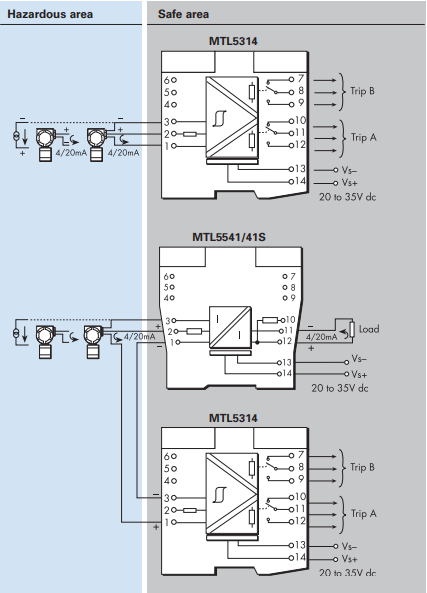
The MTL5314 connects to a 2- or 3-wire 4/20mA transmitter or current source located in the hazardous area. It supplies one or two configurable alarm signals to the safe area via changeover relays. Each relay may be configured individually to signal an alarm condition (relay de-energised) when the input signal is greater than or less than a pre-set value.
In addition, the MTL5314 can be connected in series to the hazardous-area side of an MTL5541 4/20mA repeater power supply (or equivalent device) to provide two trip alarm outputs direct from the transmitter signal (see schematic diagram). Looping the transmitter signal through the MTL5314 (via terminals 1 and 3) does not affect HART® communications.
SPECIFICATION
See also common specification
Number of channels
One, with two configurable alarms
Location of field equipment
Zone 0, IIC, T4–T6 hazardous area, if suitably certified
Div 1, Group A, hazardous location
Safe-area output
Two relays with changeover contacts
Hazardous-area input
Signal range: 0 to 24mA (including over-range)
Voltage available for transmitter (terminals 1 and 2)
>17V at 20mA
Current input (terminals 1 to 3)
Input resistance 25Ω maximum
Response time
<75ms
Trip-points
Trip-points can be adjusted by the user via multiturn potentiometers accessible on the top of the unit. Trip-point range 0.5 to 22mA Effective resolution 20μA Trip-point drift with temperature 1.5μA/°C max. Hysteresis min 1% of trip-point range max 1.7% of trip-point range
Relay type
Single pole, changeover contacts Note: reactive loads must be adequately suppressed
Relay characteristics
Contact rating 250V ac, 2A, cosø >0.7 40V dc, 2A, resistive load Contact life expectancy 3.3x10⁵ operations
LED indicators
Power LED green, illuminated when the power is connected to the module Status LED yellow, one per trip, illuminated when relay is energised (not tripped)
Supply voltage
20 to 35V dc
Maximum current consumption (with 20mA signal)
85mA at 24V 100mA at 20V 60mA at 35V
Maximum power dissipation within the unit
(with 20mA signal) 1.7W at 24V 1.8W at 35V
Safety description
Terminals 2 to 1 and 3 28V, 300Ω, 93mA
Terminals 1 and 3
These terminals meet clause 5.4 of EN50020 : 1994 and have the following parameters: U ≤ 1.5V, I ≤ 0.1A, P ≤ 25mW. They can be connected without further certification into an IS loop with open circuit voltage of not more than 28V. See certificate for further details.
相关文章
-

MTL1141 isolator
MTL1144 voltage/current input isolator 1 channel for 1V/5V/10V and 20mA inputs The MTL1144 is a single channel signal converter which can accept 0-1V, 0-5V, 1-5V, 0-10V, 0-20mA and 4-20mA inputs and converts the signal to 4-20mA for...
-
MTL7798
MTL7798 Power feed and protection module The MTL7798 power feed module incorporates both voltage and current sense mechanisms to protect barrier circuits by activating a solid state trip mechanism when fault or overload conditions oc...
-
MTL7744
MTL7744 2 channel proximity sensor or switch inputs with solid state outputs A dual channel version of the MTL7742. This module provides two solid state interfaces for prox/switch inputs. Power is connected via the power bus. BASIC...
-
MTL7743
MTL7743 2 channel proximity sensor or switch input and relay outputs The MTL7743 is a dual channel switch/prox sensor input barrier with a relay interface. This module is ideal for applications where high channel packing densities ar...
-
MTL7742
MTL7742 proximity sensor or switch input with solid state output The MTL7742 is a single channel switch/prox input barrier with an open collector solid state interface to the safe area equipment. The solid state switch is especially...
-
MTL7741
MTL7741 proximity sensor or switch input and relay output The MTL7741 is a single channel switch/prox input barrier with changeover relay contacts acting as the safe area interface. Relay contacts provide a universal interface capable...