

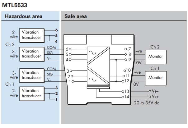
The MTL5533 repeats signals from vibration sensors in a hazardous area,
providing outputs for a monitoring system in the safe area. The interface is
compatible with 3-wire eddy-current probes and accelerometers or 2-wire current
sensors, the selection is made by switches on the side of the module.
The MTL5533 SPECIFICATION
See also common specification
Number of channels
Two
Sensor type
2- or 3-wire vibration transducer
Location of signal source
Zone 0, IIC, T4–6 hazardous area if suitably certified
Div. 1, Group A hazardous location
Hazardous-area
input Input impedance
(terminals 2 & 3, 5 & 6): 10kΩ
Transducer supply voltage, 3-wire (terminals 3 & 1 and 6 & 4)
Transducer supply current, 2-wire
3.3mA (nom.) for 2-wire sensors, user selectable by switch
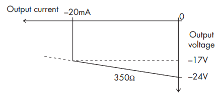
Signal range Minimum –20V, maximum –0.5V
DC transfer accuracy at 20°C <±50mV
AC transfer accuracy at 20°C 0
Hz to 1kHz: ±1%
1kHz to 10kHz: –5% to +1%
10kHz to 20kHz: –10% to +1%
Temperature coefficient
±50ppm/°C (10 to 65°C)
±100ppm/°C (–20 to 10°C)
Voltage bandwidth
–3dB at 47kHz (typical)
Phase response
<14µs, equivalent to:
–1° at 200Hz
–3° at 600Hz
–5° at 1kHz
–50° at 10kHz
–100° at 20kHz
Safe-area output impedance
<20Ω
LED indicator
Green: power indication
Supply voltage 20 to 35V dc
Maximum current consumption (10mA transducer load/ch)
130mA at 24V
Maximum power dissipation within unit
2.7W
Safety description
Terminals 3 to 1 and 6 to 4
Uo=26.6V Io=94mA Po=0.66W Um = 253V rms or dc
Terminals 3 to 2 and 6 to 5
Non-energy-storing apparatus ≤1.5V, ≤0.1A and ≤25mW
Note -
Refer to the Instruction Manual for recommendations on mounting of these modules.
A minimum spacing of 10mm must be applied between these and any other modules on the DIN-rail.
Maximum ambient temperature with this spacing is 50°C
| MTL5533 Product Termination Notice and 'Last time buy' | |||
| Statement issued | Product | Last time buy | Replacements and notes |
| 06 September 2016 | MTL5533 | 31st March 2017 | Convert to 2 x MTL5531 |
相关文章
-
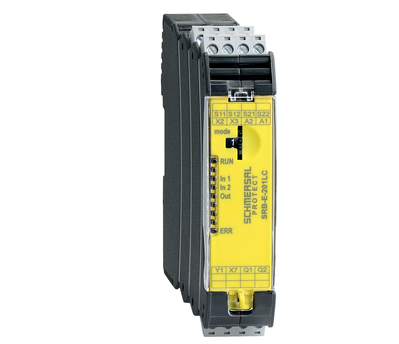
Schmersal Safety Relay Module SRB-E
Widely Applicable Safety Signal Processing The new generation of safety relay modules, the PROTECT SRB-E series, comes in 8 models, achieving safety ratings of Cat.4 / PLe (compliant with EN ISO 13849-1 standard) and SIL 3 (compliant...
-
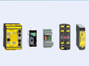
Schmersal Safety Installation System
Providing Optimal Solutions for Diverse Applications The new Schmersal safety installation system simplifies the rapid connection of safety switches to existing complex equipment systems, significantly reducing wiring errors and cost...
-

Schmersal SLC/SLG 440 IP69K Series Safety Light Curtains
Schmersal SLC/SLG 440 IP69K Series Safety Light Curtains, Ideal for the Food Industry The Schmersal SLC/SLG 440 IP69K Series: Hygienic and Durable Schmersal Group has developed a new series of safety light curtains and ba...
-

Schmersal Safety Light Curtain SLC44/COM BLE
Bluetooth Interface for Safety Light Curtains Schmersal Group has introduced the SLC440/COM, a pioneering safety light curtain equipped with a built-in Bluetooth Low Energy (BLE) interface. This photoelectric protective device (AOPD)...
-
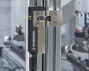
SCHMERSAL Introduces the World's Smallest Electromagnetic Safety Lock
The SCHMERSAL AZM40, measuring 119.5 x 40 x 20 mm, boasts the title of the world's smallest electromagnetic safety lock. This makes it especially suitable for small safety gates and flaps. Thanks to its 180° flexible actuator, the...
-
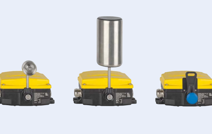
SCHMERSAL Modular Switch Platform HDS
SCHMERSAL Group has introduced a brand-new HDS series of switches tailored for the heavy industry. This modular product line, integrating multiple functions, finds extensive applications across various heavy industries. Based on a s...